
You can conduct interesting experiments with this temperature-dependent oscillator. Tone pitch depends upon the temperature of a sensor. The sensor is a common general-purpose silicon diode. The reverse resistance of this diode is slight, dependent on the junction temperature. The circuit can operate in a temperature range typically between -20 and +100 degrees Celsius.
Frequency range depends upon Cl. This component can be altered in a large range of values. Values between 0.01 and 0.47uF can be substituted to produce tones in the audio range.
If you want to produce "clicks" with a rate dependent upon the temperature of the sensor, try capacitors with values between 0.47 and 1uF. Metal film or ceramic capacitors can be used in this circuit.
By adjusting Pl you can put the oscillator near the point where it begins to run.
Then, any temperature rise will trigger the oscillator, making it operate as a temperature alarm.
The circuit can be powered from two or four AA cells, and current drain is low.
The sensor is any general-purpose silicon diode. The diode can be protected against moisture and water.
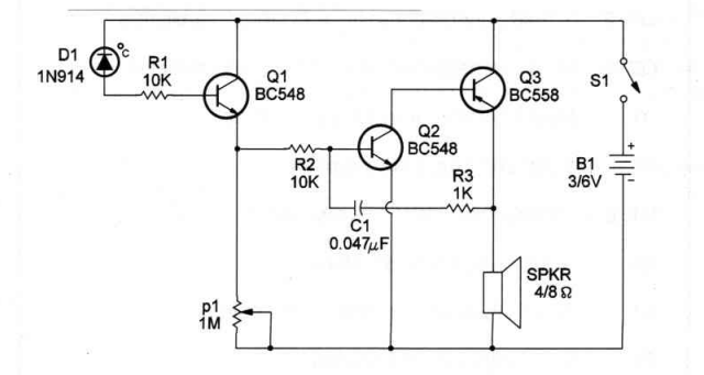
The schematic diagram of the Temperature-Controlled Oscillator is shown in
circuit. The sensor can be wired to the circuit by a long twisted-pair wire for remote operation.
Components layout, using a terminal strip as chassis, is shown in circuit. As the circuit is intended for experimental purposes, you can also mount it on a solderless board.
Position of polarized components, such as the diode and power supply, should be observed.
Parts List - Temperature-Controlled Oscillator
Q1, 2 - 8C548 general-purpose NPN silicon transistors
Q3 - 8C558 general-purpose PNP silicon transistor
D1 - 1N914 general-purpose silicon diode
P1 - 1,000,000 ohm potentiometer
R1,2 - 10,000 ohm, 114W,5% resistors
R3 - 1 ,000 ohm, 1/4W,5% resistor
Cl - 0.047uF ceramic or metal film capacitor
S1 - SPST toggle or slide switch
81 - 3V or 6V - two or four AA cells
SPKR -4or Iohms-2or 4in. loudspeaker
No comments:
Post a Comment