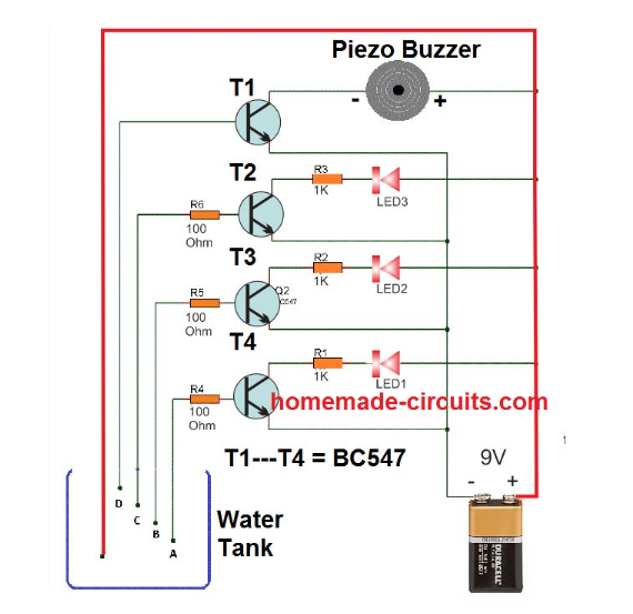
Circuit Description:
The circuit consists of four separate circuits, each responsible for indicating a different water level.
The first circuit has a red LED and a BC547 transistor. When the water level reaches the first sensor, the circuit is completed and the red LED glows.
The second circuit has a yellow LED and a BC547 transistor. When the water level reaches the second sensor, the circuit is completed and the yellow LED glows.
The third circuit has a green LED and a BC547 transistor. When the water level reaches the third sensor, the circuit is completed and the green LED glows.
The fourth circuit has a buzzer and a BC547 transistor. When the water level reaches the fourth sensor, the circuit is completed and the buzzer starts beeping.
Operation:
When the water level is below the first sensor, all of the LEDs are off and the buzzer is silent.
As the water level rises, it first reaches the first sensor. This completes the circuit for the red LED, and it begins to glow.
As the water level continues to rise, it reaches the second sensor. This completes the circuit for the yellow LED, and it begins to glow.
As the water level continues to rise, it reaches the third sensor. This completes the circuit for the green LED, and it begins to glow.
Finally, if the water level reaches the fourth sensor, this completes the circuit for the buzzer, and it begins to beep.
Additional Notes:
The values of the resistors can be adjusted to change the sensitivity of the circuit.
The number of sensors can be increased or decreased to monitor more or fewer water levels.
The circuit can be powered by a DC power supply instead of a 9V battery.
Components:
9V battery
4x 220Ω resistors
3x LEDs (red, green, yellow)
1x buzzer
4x BC547 transistors
Breadboard
Jumper wires
Testing and Calibration
Once your circuit is assembled, test it in a controlled environment. Adjust the programming and sensor placement as needed to achieve accurate readings.
Conclusion
Building a water level sensor circuit is a rewarding DIY project, providing valuable insights into electronics and automation. This schematic serves as a foundation, and you can customize it based on your specific requirements. Enjoy exploring the world of water level sensing and incorporating this technology into your projects!


No comments:
Post a Comment