
SET-RESET FLIP-FLOP (E)
With this pQect we can show how two NAND gates of a 7400 lC (TTL Integrated Gircuit) can be wired to perform as an R-S flip-flop.
This circuit is a pulse-triggered flip-flop that needs negative-going pulses to be
triggered. This circuit operates as follows: as we see, it haltwg_outngls; a
nolmd output called O (LED1) and an inverted output called O (LED2).When
one output is 1 the other necessarily will be 0 and vice-versa because they are
complementary.
The circuit has also two inputs named S (SET) and R (RESET) as shown in
the schematic diagram, where the trigger signals are applied.
R input is wired to Q output and S input is wired to Ooutput, forming aclosedloop for the digital signals.
When a negative-going trigger pulse is applied to S inputhe output Q swingi
to the 1 staie. As thistutput is wired to R input, the 1 state causes output Q
to fall to a 0 level. But Q output is also wired to S input causing afeedbackthat
makes its output remain at 1 also atter the trigger pulse has disappeared. To
trigger the flip-flop again, changing the output states, we should apply a negap!-going pulse to R input.This pulse causes the output to go to 1 , and as this
output is wired to R input, the trigger pulse also causes the output Q to go to
0level.
Azero in this output goes to R input, and also after the trigger pulse disappears the outputs remain in their states.
See that the circuit has two stable states, and we only can change these
states with set or reset (S or R) negative-going pulses applied to its inputs.
Our project is a manually-triggered flip-flop and can be constructed wiring a
switch to the R-S inputs as shown in Figure 1.
Logic states are indicateqby two LEDs. LED1 glows with a 1 at Q output and
LED2 glows with a 1 at d outPut.
Ffd0crz sH-i$fff,llHrr
The circuit must be powered by a S-volt regulated power supply as it uses a
TTL lC. Current requirements range typically from 5 to 15 mA.
Components placement on a small printed-circuit board is shown in Figure 2.
Experiments like this can also be performed on what electronics experimenters call "breadboards". These are boards on which the parts of experiments
can be temporarily assembled. By using breadboards it is not necessary
solder the components. This is why they are also called "solderless boards"
The circuit can be used to teach much about flip-flops, used in computers as
counters and in memories and many other applications.
Observation: In digital electronics an electrical signal is either high or low.
These two states ale used to represent binary bits 1 and 0. Since digitalogic
lOs operate from a single-ended power supply, a high state represents a
voltage near the supply voltage and a low state represents avoltage near 0V'
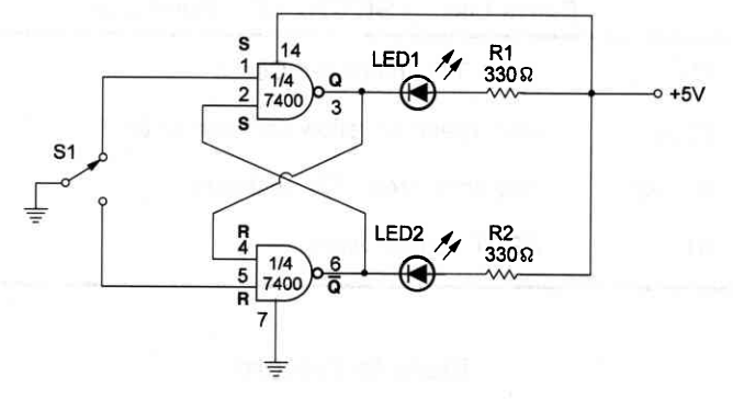
Panrs Lsr - SET-RESET FUP-FIoP fC1 - 74OO TTL Integrated Gircuit LEDs - Red, green or yellow common LEDs R1, R2 - 330 ohm, 114W,5Y" resistors 51 - SPDT toggle switch


No comments:
Post a Comment