This circuit can be used to controlthe amount of current in an incandescent
lamp and also a DC motor. lf you change the amount of current through a
lamp you change its brightness. And if you change the amount of current
through a DC motor you change its speed. lnput voltage can range from 6 to
12 volts and current drain in the output is up to 2A. You can also use this
circuit in the output of a 6V or 12V fixed power supply, converting it into a
variable 0to 6 volt or 0 to 12 volt supply.
The power transistor should be mounted on a heatsink. The circuit can be
housed in a small plastic box and the heatsink with the transistor fixed on the
outside.
robotics to control DC motor speed along a wide range of values. Also, several experiments involving current flow control can be performed using this
circuit.
The circuit acts as a variable resistor or rheostat with the principal current
flowing through the transistor and the control current flowing through the potentiometer. Current through the potentiometer is only a few milliamperes.
The schematic diagram of the DC dimmer is shown in Figurc t. Ql is an
NPN power transistor and the principal component used in this project.
Components layout is shown in Figure 2. Thetransistor does not show on
the heatsink, however.
Equivalent transistors can be used, but take care with the maximum current
they can control. Types such as TlP31 and TlP41 can be used to control
lamps up to 2 amperes. Also, a further modification iRl value must be
made to ensure that, when P1 is set near its minimum value, that current is
flowing through the lamP.
lf equivalent transistors are used, take care with their terminal positions, as
they can be ditferent.
Parts List - DC Lamp Dimmer
Q1 - 2N3055 Silicon NPN power transistor
P1 - 4,700 ohm potentiometer
R1 - 470 ohm, 2W,.5"/" resistor
F1 - 5A fuse
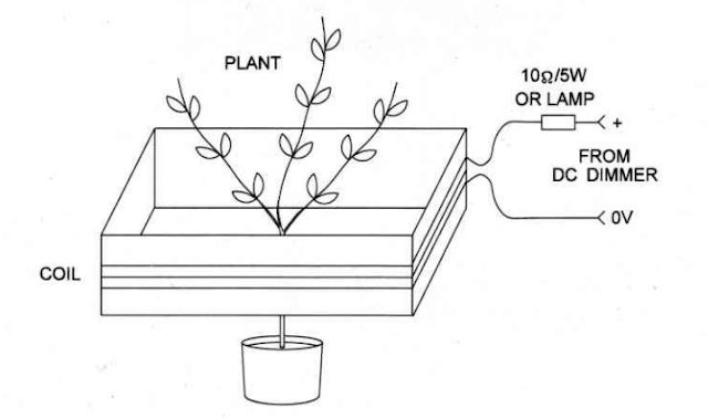
Figure3 shows how this experiment can be arranged.
The coil is formed by 10 to 50 turns of common No.1 Ito 22wire around a
cardboard box or wood form. An ammeter in series with the coil circuit can be
used to control the amount of current used in the experiment.
Remember that too much current will cause the coil and the transistor to
overheat. lt is a good idea to add a lamp in series with the coil circuit. The
lamp will add resistance to the coil circuit, reducing current flow to a safe
level.


No comments:
Post a Comment